
LogoStampForce
Servo-Driven Stamping Systems — Est. 1979

Ten Million
Strokes.
Same Mark.

Progressive dies. Transfer presses. Deep-draw stainless runs. Stamping systems engineered to micron tolerances for tier-one automotive, appliance OEMs, and job shops that cannot afford variance.

SF-2500T SERVO PRESS — CROSS SECTIONREV 4.2
2,500 TONBOLSTER PLATESLIDE ASSEMBLYPROGRESSIVE DIE STATIONSERVO MOTOR HOUSING4,200 mm
StampForce Mfg. SystemsDrawing No. SF-2500T-CS-001Scale 1:40
2,500TON
Max Tonnage
±0.005mm
Repeatability
120SPM
Max Strokes
47YRS
Years in Service
Progressive Die SystemsTransfer Press EngineeringDeep Draw ToolingFine BlankingServo RetrofitFEA SimulationIATF 16949 Qualified±0.005 mm Repeatability2,500 Ton CapacityDie Life EngineeringProgressive Die SystemsTransfer Press EngineeringDeep Draw ToolingFine BlankingServo RetrofitFEA SimulationIATF 16949 Qualified±0.005 mm Repeatability2,500 Ton CapacityDie Life Engineering
System Lifecycle / 7 Phases

From Drawing Release
to Production Stability.

Each card represents a discrete phase of the stamping system lifecycle. Click any card to expose the engineering depth beneath.

Phase 01

Engineering Consultation

Part analysis, tonnage calculation, and die concept review before a single drawing is cut.

4–6 wkAvg. Quote Turnaround
Technical spec
Phase 01 / Spec Sheet

Our applications engineers review your part geometry against material spec sheets. Progressive, transfer, or compound — we determine the correct press architecture before the proposal.

  • Formability index analysis
  • Material springback calc
  • Die station count optimization
4–6 wkAvg. Quote Turnaround
Phase 02

FEA Simulation

Finite element analysis validates forming sequences and identifies thinning risk before die steel is cut.

Technical spec
Phase 02 / Spec Sheet

Simulation data drives die face geometry, blank development, and binder force calculations. Clients receive full simulation reports with heat maps and strain distribution overlays.

  • AutoForm / Dynaform models
  • Thinning < 15% threshold
  • Wrinkling suppression maps
~30%Reduction in Die Try-Out Iterations
Phase 03

Die Design

Progressive and transfer die design to D2 / M2 / carbide tooling standards with full tolerance stack analysis.

Technical spec
Phase 03 / Spec Sheet

Die designs are released in CATIA V5 / Solid Edge. Full tolerance stack reports accompany every build package, with GD&T callouts matched to part print requirements.

  • ±0.003 mm punch/die clearance
  • Carbide inserts for <0.5 mm features
  • Standardized SMED quick-change bases
≥2MDesigned Tool Life (Strokes)
Phase 04

Machine Build

Servo-driven and mechanical press assembly in our 180,000 sq ft facility, with full traceability on every component.

Technical spec
Phase 04 / Spec Sheet

Critical components — gibs, crankshafts, connection rods — are manufactured in-house on Mazak and DMG Mori CNC equipment. Incoming material certs are logged to serial number.

  • Servo motor: Siemens 1FT7 series
  • Slide parallelism ≤ 0.02 mm
  • Hydraulic overload protection std.
180k ft²Manufacturing Floor Space
Phase 05

Runoff Testing

Full-speed production runoff at rated tonnage before shipment, with SPC data delivered to the customer.

Technical spec
Phase 05 / Spec Sheet

Every press ships with a runoff report including SPC control charts, hit-to-hit tonnage plots, and dimensional inspection data on first-off parts. No surprises on your floor.

  • 100k-stroke runoff minimum
  • Cpk ≥ 1.67 on critical dims
  • Tonnage signature recording
Cpk ≥ 1.67Runoff Acceptance Criterion
Phase 06

Installation & Commissioning

StampForce field engineers handle rigging, leveling, electrical tie-in, and operator qualification at your facility.

Technical spec
Phase 06 / Spec Sheet

Installation teams are certified millwrights and controls engineers. Commissioning includes a full I/O checkout, safety circuit validation, and a two-day operator training program.

  • Foundation bolt-pattern supplied
  • Leveling tolerance ±0.05 mm/m
  • OSHA 1910.217 compliance audit
< 5 daysTypical Installation Window
Phase 07

Aftermarket Support

OEM parts, rebuild programs, servo retrofits, and 24/7 remote diagnostics for the full press lifecycle.

Technical spec
Phase 07 / Spec Sheet

The support team carries 95% of wear parts in stock. Remote diagnostics via secure VPN allow our engineers to pull alarm history and drive parameters without site visits.

  • 10-year parts availability guarantee
  • 4-hr emergency response SLA
  • Servo retrofit for mechanical press
95%Parts Fill Rate (Same Day)
Technical Library / Ungated Resources

The Engineering
Comes First.

No email required. These resources exist because fluency earns trust — and trust earns the project.

COMPARISON CHART

Servo vs. Mechanical Press: Full Specification Matrix

Side-by-side comparison of 14 performance parameters — energy consumption, stroke programmability, die protection sensitivity, and TCO over 10-year horizon.

PDF8 pagesUpdated Q1 20261.2 MB
WHITE PAPER

Progressive Die Design for AHSS: Managing Springback in 980 MPa Steels

Technical paper covering compensation strategies, overbend geometry, and die face optimization for advanced high-strength steel forming in automotive body-in-white applications.

PDF24 pagesTechnical3.8 MB
INTERACTIVE TOOL

Die Life Calculator

Input your material, thickness, feature geometry, and production volume to estimate tool life in strokes and annual regrind cost. Includes D2, M2, and carbide tooling comparison.

Web ToolNo LoginInstant Results
CASE STUDY

Tier-1 Automotive: 47% Scrap Reduction on Deep-Draw Door Panel Run

How FEA-driven blank development and servo-controlled binder force eliminated edge cracking on a 1.5 mm galvanneal run at 45 SPM. Includes SPC before/after data.

PDF12 pagesAutomotive2.1 MB
SPEC SHEET

SF-Series Servo Press: Full Technical Specifications

Complete dimensional drawings, electrical requirements, pneumatic specifications, and performance curves for the SF-800T through SF-2500T servo press range.

PDF32 pagesCAD Available6.4 MB
WHITE PAPER

SMED Implementation on Transfer Press Lines: A Practitioner's Guide

Step-by-step methodology for reducing die changeover from 4 hours to under 20 minutes on transfer press applications. Includes standardized tooling requirements.

PDF18 pagesOperations2.7 MB
Industries Served / 3 Primary Segments

Built for the Buyer
Who Reads the Print.
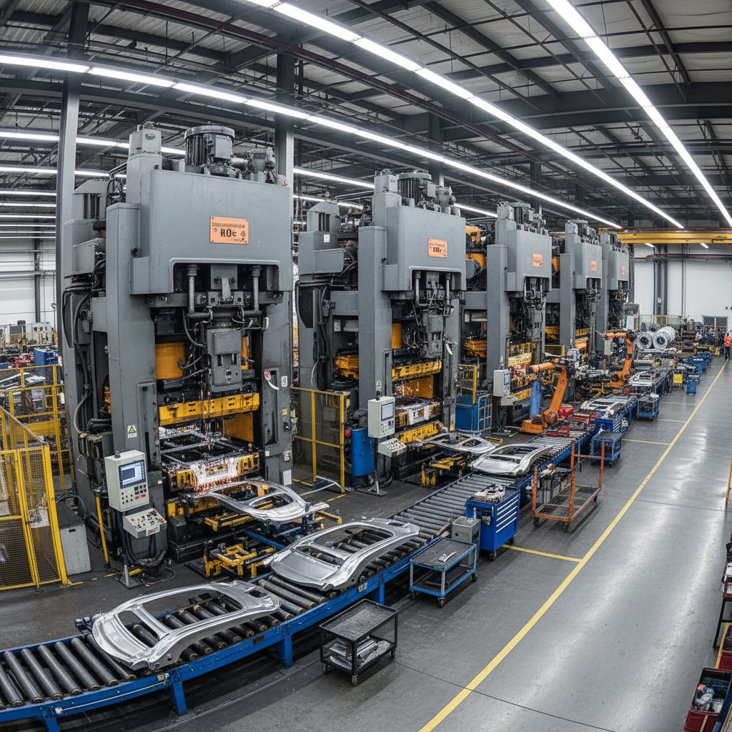
Automotive stamping press line producing chassis panels in a tier-one manufacturing facility
Tier-1 Automotive
Body-in-White / Chassis

Tier-1 Automotive

SF-1200T ProgressiveSF-2500T Transfer

Structural brackets, door-inner panels, seat tracks, and chassis reinforcements in AHSS, galvanneal, and hot-stamped boron steel. Press lines qualified to IATF 16949 with full PPAP documentation.
Material Range
HSLA 340 → PHS 1500
Typical Tonnage
800T – 2,500T
Die Type
Progressive / Transfer
Quality Std.
IATF 16949 / AIAG
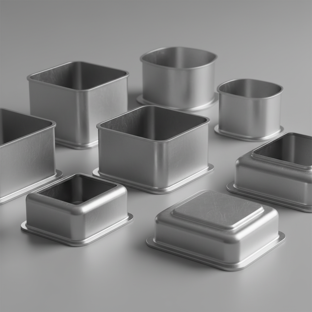
Stainless steel deep-draw stamping components for appliance manufacturing showing formed housings
Appliance OEM
Deep-Draw / Fine Blanking

Appliance OEM

SF-800T TransferSF-600T Deep Draw

Washer tubs, compressor housings, refrigerator liners, and motor end bells in 304 / 430 stainless and aluminized steel. High-SPM transfer presses optimized for deep-draw ratios up to 2.4:1.
Material Range
304 SS / 430 SS / Aluminized
Typical Tonnage
400T – 1,200T
Die Type
Transfer / Deep Draw
Draw Ratio
Up to 2.4:1 LDR
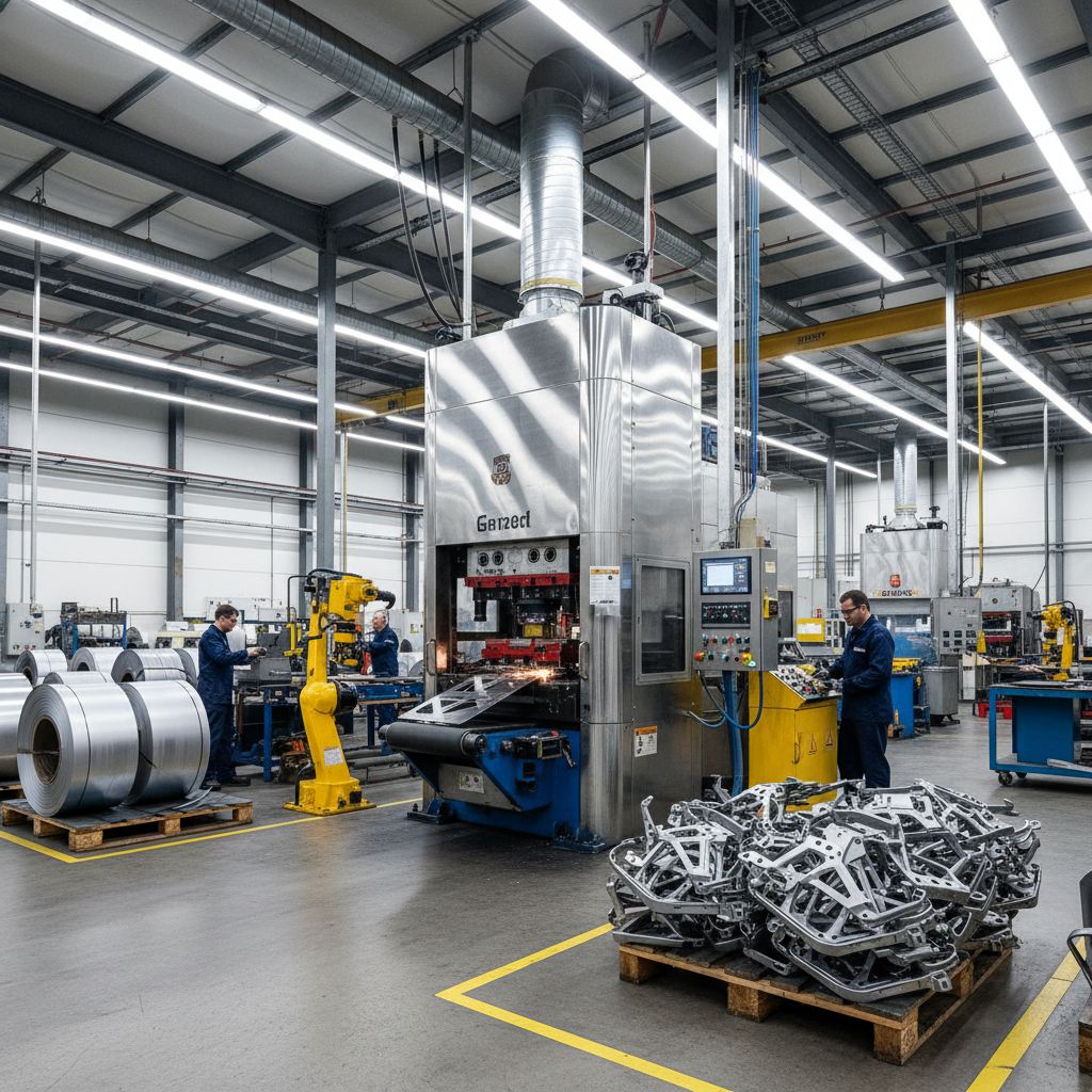
Metal stamping job shop floor with servo-upgraded press producing precision sheet metal components
Metal Stamping Job Shop
Servo Retrofit / Upgrade

Metal Stamping Job Shop

Servo Retrofit KitSF-400T Mechanical

Job shops running aging mechanical presses face rising scrap rates and lost quoting capacity on complex parts. StampForce servo retrofit packages convert existing frames to full servo-drive with 12-month payback targets.

Retrofit Range
150T – 800T frames
Payback Target
< 12 months typical
Downtime
8–12 days conversion
Warranty
3-yr servo system
Gated Resource / Engineering Guide

Tonnage Selection
Guide.

48 pages. Covers tonnage calculation methodology for progressive, transfer, deep-draw, and fine-blanking applications. Includes material conversion tables, safety factor guidance, and press selection decision trees.

Tonnage calculation formulas for 6 common operations
Material strength tables: AHSS, stainless, aluminum alloys
Progressive vs. transfer press selection decision tree
Deep draw force and blank development methodology
Servo vs. mechanical press ROI model (10-yr horizon)
Die cushion and blank holder force calculations
3,400+Downloads in 2025

"We used the tonnage calc methodology to right-size our new transfer line. Saved us from buying 400 excess tons."
— David Kowalski, Process Eng., Magna Metalforming

Access Request / Tonnage Selection Guide v4.1

No spam. Guide delivered instantly. Applications engineer follow-up is optional.